Here are my notes on creating a 3-beam Yagi antenna for 2m out of a tape measure and some PVC pipe.
Parts
- Tape measure, at least 10′ long, steel, 1″ wide
- 24 inches 3/4″ schedule 40 PVC pipe
- 1 3/4″ schedule 40 PVC T-junction
- 2 3/4″ schedule 40 PVC X-junction
- 6″ 14AWG solid copper wire
- 6 3/4″ stainless steel hose clamps
- 3+ feet RG-58 coax cable
- PL-259 connector
- Electrical tape
- Solder and flux pen
Tools
- Multimeter to verify electrical connections
- Cutting implement (hack saw) for cutting the PVC
- Shears to cut tape measure and wiring
- Wire strippers to remove insulation
- Soldering iron for electrical connections
- Sandpaper for removing coating on tape measure
- Screwdriver to tighten hose clamps
Important Dimensions
- Reflector element is 41 3/8″
- Director element is 35 1/8″
- Drive elements are 17 3/4″ each, separated by approximately 1″
- Hairpin match is 5″ long, shaped like a U with 3/4″ between legs
- Center of Reflector to center of Drive is 8″, PVC between joints approximately 6 3/4″
- Center of Drive to Director is 12 1/2″, PVC between joints approximately 11 1/4″
Instructions

Cut the tape measure to the appropriate lengths using metal shears. Reference the dimensions above.

Use electrical tape to cover both ends of the director and reflector, and the outer edges of each drive element, to prevent injury on the sharp edge.

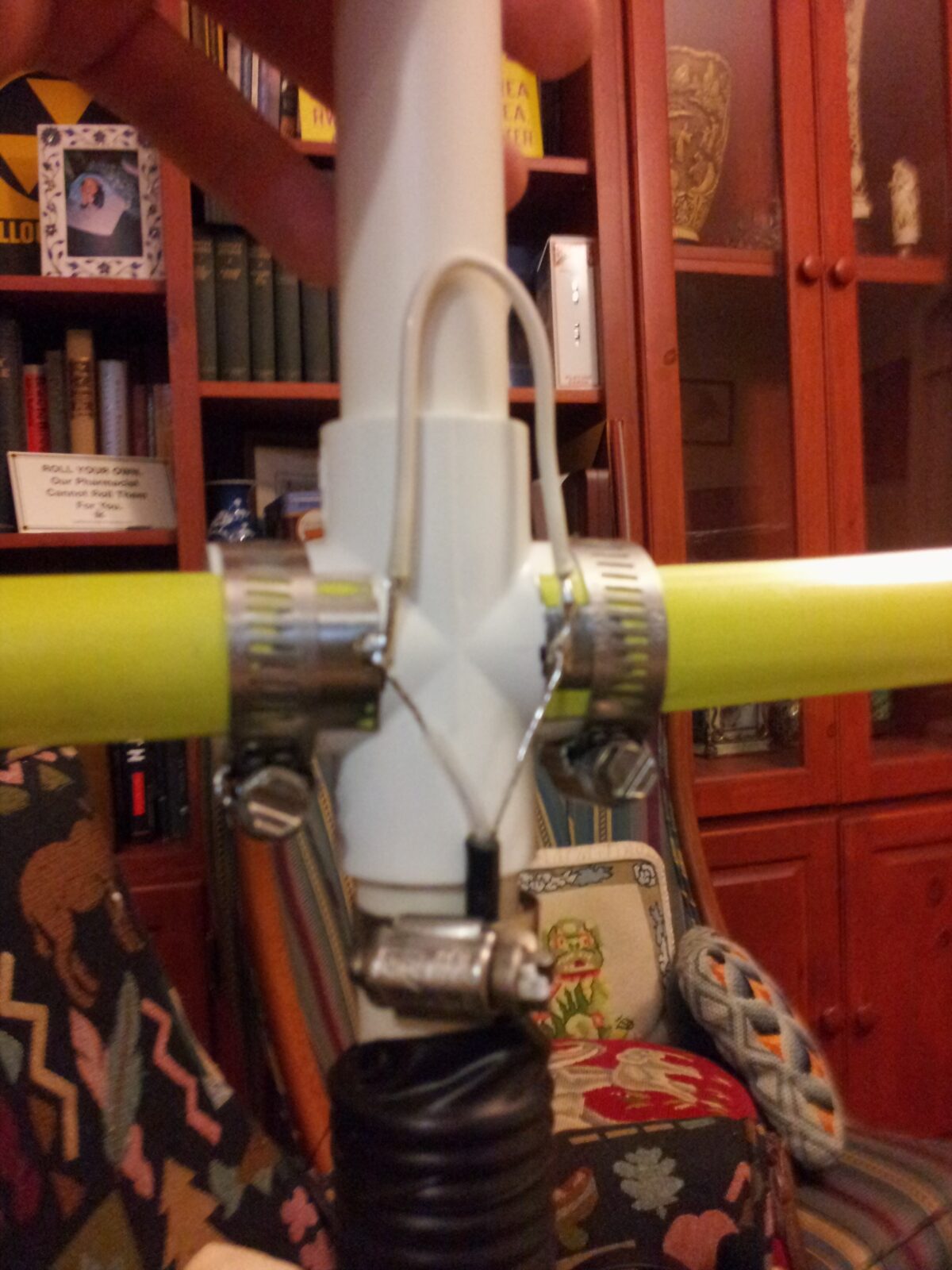
Cut the PVC pipe to appropriate lengths and assemble as shown in the photo, so that the centers of the junctions meet the element separation lengths described above. The T junction will hold the director element. Optionally, an extra piece of PVC can be inserted into the reflector element’s X junction to serve as a handle. Assemble the PVC components, using friction to hold the joints in place, or use a PVC plumbing glue to attach them permanently.

Center the director and reflector elements over their respective junctions and clamp them in place with the hose clamps, making sure the elements are centered. Did I mention they should be centered? The short Director goes on the T fitting further from the center.

Use the sandpaper to removing the coating on the inner edges of the drive elements. Form the 14AWG wire into a U shape as described, strip the insulation off the ends, and tin the tips. Prepare the coaxial cable similarly. Tin the sanded ends of the drive elements, then loosely clamp them in place with about 1“ separation. Quickly, so as not to melt the pvc underneath, solder the wire ends and the coax ends to each of the drive elements.
The solder may have trouble sticking to the tape. If you encounter this, try sanding the surface a little more and wiping it down with alcohol, letting it dry, then try again.

Wrap the remaining coaxial cable around the PVC beam towards the reflector element, making 8 turns in a single layer, all touching tightly. Wrap the loops in electrical tape to hold the balun’s shape. Or maybe it’s a choke. Or both? Beats me.

At the end of the RG-58, attach a PL-259 male connector. Connect the antenna to an SWR meter and drive it with no more than 50W. Adjust the gap between the driven elements, making sure they stay symmetric, until the SWR is minimized for the desired frequency. Tighten down the hose clamps for the driven element and recheck SWR readings. Your antenna is ready to use!
Thanks Laura Block for doing this build with me and posing for pictures!
Update: 7 years later this antenna still works.