Here are my notes on creating a “Slim-Jim” 2m modified J-pole antenna out of TV antenna line.
Parts
- 60“ 300-ohm twin-lead non-windowed TV antenna line
- 36” RG-58 coaxial cable
- Electrical tape
- Solder and flux pen
- PL-259 connector
Tools
- Multimeter to verify electrical connections
- Tape measure to check lengths
- Wire cutters for cutting lengths
- Wire strippers/knife for removing insulation
- Soldering iron for making electrical connections
Important Dimensions
- Total antenna finished length of 300-ohm twin-lead: 58″
- Initial 300-ohm twin-lead: 60″
- Length from bottom of J to notch: 19″
- Width of notch: 1″
- Length from bottom of J to feedline attachment points: ~4″
Instructions

Take your 300-ohm twin-lead and measure out 60 inches. Strip 1 inch of insulation off each end, and twist the two leads at each end together into a rounded U-shape of minimum length.

Solder the ends together, then cover the exposed copper with electrical tape.

Measure 19“ from the bottom end of the antenna (at this point, either end, doesn’t matter), and cut ONE SIDE of the line. Measure up 1” from that cut, and make another. Remove the now-isolated 1“ of copper from the antenna.

Next, measure about 4” from the bottom of the antenna and strip the insulation from BOTH sides of the antenna. Be sure not to sever the copper.

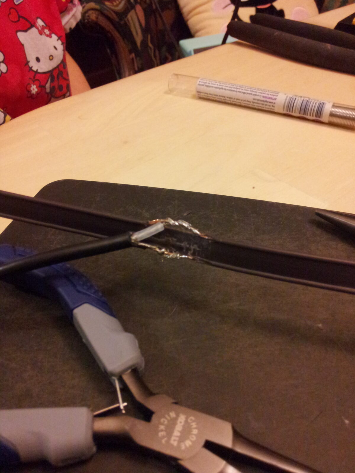
Prep the ends of the coaxial cable for attachment to the antenna. Remove a small amount of insulation from the inner conductor, and a further small amount from the outer conductor. Move the shielding braid to one side and twist together.

The shield is attached to the side with the notch, while the center conductor is attached to the unnotched side. Make sure they don’t cross electrically. Hold the connections in place using electrical tape. Don’t solder them yet!

Wind 7-10 loops of coax around a 3/4“ diameter PVC pipe and wrap the coil in electrical tape to hold it in place. The loops should be tight around the PVC and touching each other. This will create an air-choke balun to match the balanced antenna to the unbalanced feed line; in effect, this keeps the feed line from radiating RF as if it were part of the antenna. I think. Look, I’m not an RF engineer here, ok?
Attach the PL-259 connector to the other end of the coax and connect it to the SWR meter and test rig. Using minimum power, tune the antenna for minimum SWR on the desired frequency by moving the connection points of the coax to the antenna. Be sure to keep the connection points parallel on the twin-lead as you make the adjustments. When you’re satisfied, solder the coax connections in place, and you’re done.
Thanks to Laura Block for doing this build with me!
Update: 7 years later this antenna still works.